Reading WATERMARK Sensors
Overview
The WATERMARK Soil Moisture Sensor measures electrical resistance inside a granular matrix to determine soil water tension. Originally developed in the 1980s, the sensor has been read by many different methods and devices — by IRROMETER as well as third parties.
The sensor presents as a variable resistor whose value changes with soil water tension. Three methods are commonly used to determine that resistance:
- Voltage divider (ADC) — The most common approach. A known series resistor and an analog input are used to calculate sensor resistance from the measured voltage.
- Capacitor charge time — A known capacitor is charged through the sensor and the time to reach a logic threshold is measured. Useful on microcontrollers with only digital I/O and no ADC.
- Purpose-built adapters — For standard output formats (0–3V analog, SDI-12), see the adapter modules on the sensors page.
Once resistance is known, it is converted to soil water tension (kPa / centibars) via calibration equations or look-up tables.
Sensor Power
AC excitation is the simplest approach for reading WATERMARK sensors. Alternating polarity prevents charge buildup that would both offset readings and degrade the electrodes over time. Where AC is impractical, two DC alternatives are acceptable:
1. Pseudo-AC Short Pulse
A "pseudo-AC" is created by alternating the current direction of a brief DC excitation for equal amounts of time. Two output pins are used — one as source, one as ground — and their states are swapped between readings. The second reading reverses the charge of the first, leaving the sensor with no accumulated potential. Excitation should not exceed 50 ms total; the measurement should be taken within 100 μs.
2. DC Short Pulse
If DC current is applied without alternating polarity, excitation must not exceed 50 ms and the reading should be taken 100 μs to 200 μs after excitation is applied. Delaying beyond 200 μs will build a charge offset on the sensor, shifting the measured resistance and reducing electrode life. After reading, short the leads together or short the powered side to ground for 30 seconds to remove any accumulated DC potential.
Sensor Isolation
Devices reading WATERMARK sensors must isolate the sensor reading circuit from any earth ground. Mains-powered devices require transformer isolation to prevent a loop to ground through nearby equipment. Any communication line permanently connected to another grounded device requires optical isolation. If a ground loop exists, readings will be incorrect and current leakage will quickly destroy the sensor electrodes.
Battery-powered devices are more naturally isolated, but grounds for lightning protection can create the same problem.
When reading multiple sensors, the circuit must also isolate sensors from each other. The wet soil in which sensors are installed creates a conductive path between them. Without isolation, a device may be reading partially or fully between electrodes in different sensors rather than within each sensor.
Sensors must be powered individually and their grounds isolated from one another. Even when powered individually, an open ground path to an unpowered sensor must not be permitted. Multiplexers are the standard approach for opening and closing the appropriate channels.
Caution: WATERMARK sensors provide a direct conductive path from earth to any connected device. Zener or TVS diode protection on all sensor lines is strongly recommended, though omitted from the examples below for clarity.
Resistance Measurement
Method 1: Voltage Divider (ADC)
The voltage divider is the most common reading circuit. A known series resistor Rx and an analog input pin are used to calculate sensor resistance from the measured voltage.
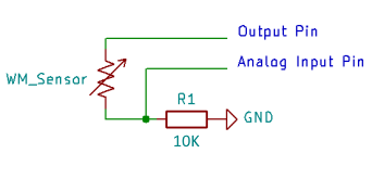
Fig. 1 — Basic voltage divider using a digital output pin and analog input
Where Vs is supply voltage, A1 is the analog measurement, and Rx is the known series resistor:
For pseudo-AC readings, two measurements are taken with reversed excitation and averaged:
RB = Rx × V2 / (Vs − V2) (Direction 2)
R = (RA + RB) / 2
Method 2: Capacitor Charge Time
On microcontrollers that lack an ADC or where a simpler circuit is preferred, sensor resistance can be determined by measuring the time for a known capacitor to charge through the sensor to a logic-high threshold (typically Vcc × 0.63 for one RC time constant, or a fixed threshold like 1.65V on a 3.3V system).
The RC time constant τ = R × C. Measuring the charge time T directly gives:
For the pseudo-AC requirement, charge and discharge the capacitor through the sensor in alternating directions between readings. A discharge resistor to ground should be included to ensure the capacitor is fully discharged before each measurement. This method works well on devices like the ESP32 touch peripheral or any GPIO with a timer, and avoids the ADC nonlinearity concerns of the voltage divider approach.
The capacitor charge method requires a stable, known capacitor value. Ceramic capacitors vary with temperature and voltage; use a film or C0G/NP0 ceramic type for best accuracy. Typical values are 1 μF to 10 μF depending on the expected resistance range.
This method also offers better conducted noise immunity on long cable runs. The voltage divider approach measures a voltage level, which is susceptible to resistive noise coupling along the cable. The charge time method measures a time interval, so conducted interference must be sustained long enough to meaningfully shift the threshold crossing — brief transients have little effect. This makes it a practical choice for installations with cable runs of 30 meters or more.
Calibration
Once resistance is known, a calibration equation converts the value to soil water tension (kPa). The most widely used calibration is the one developed by Dr. Clinton Shock (1998), covering the range of 10 to 100 kPa:
Where R is resistance in kΩ and T is temperature in °C. Linear extrapolations are typically used below 10 kPa and above 100 kPa. A fully saturated sensor measures approximately 550 Ω.
Temperature affects the measured resistance. A default value of 24 °C can be used in the absence of temperature data; a temperature sensor input improves accuracy. The extended calibration used in IRROMETER devices covers a wider range with three segments:
int myCBvalue(int res, float TC, float cF) {   // res in ohms, TC in deg C, cF = calibration factor

    int WM_CB;
    float resK   = res / 1000.0;
    float tempD  = 1.00 + 0.018 * (TC - 24.00);

    if (res > 550) {
        if (res > 8000) {                           // high range: above 8 kΩ
            WM_CB = (-2.246
                     - 5.239  * resK * tempD
                     - 0.06756 * resK * resK * tempD * tempD) * cF;
        } else if (res > 1000) {                    // mid range: 1–8 kΩ (Shock 1998)
            WM_CB = (-3.213 * resK - 4.093)
                    / (1 - 0.009733 * resK - 0.01205 * TC) * cF;
        } else {                                    // low range: 550–1000 Ω
            WM_CB = (resK * 23.156 - 12.736) * tempD;
        }
    } else {
        if (res > 300) {
            WM_CB = 0;                              // saturated / new sensor
        }
        if (res < 300 && res >= SHORT_RESISTANCE) {
            WM_CB = SHORT_CB;                       // 240: sensor terminal short
        }
    }
    if (res >= OPEN_RESISTANCE || res == 0) {
        WM_CB = OPEN_CB;                            // 255: open circuit / sensor absent
    }

    return WM_CB;
}
A pre-computed look-up table is available in the downloads below for use where floating point arithmetic is impractical.
Arduino Example
The example below reads one soil temperature sensor and three WATERMARK sensors using one 74HC4052 dual-channel multiplexer. Two output pins (PWM3, PWM4) select the multiplexer channel while PWM5 and PWM11 are alternated as excitation source and ground. A1 provides the analog measurement.
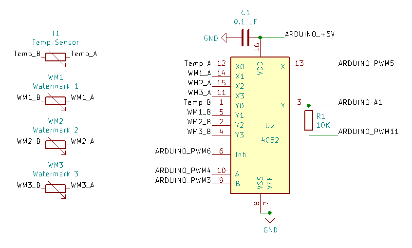
Fig. 2 — Arduino circuit reading three sensors via 74HC4052 multiplexer
Sequence
Setup: PWM6 set LOW to enable multiplexer.
Direction 1
- PWM3 and PWM4 set to sensor channel
- PWM5 set HIGH (excitation)
- Read A1
- PWM5 set LOW
Direction 2
- PWM11 set HIGH (reverse excitation)
- Read A1
- PWM11 set LOW
PWM3 and PWM4 are advanced to the next channel and the reading is repeated for each sensor. PWM6 set HIGH to disable the multiplexer when done.
Calculate Resistance
Where SenVWM1 is the analog voltage measured in Direction 1, SenVWM2 in Direction 2, and Rx is the series resistor value:
double WM_ResistanceA = Rx * (SupplyV - SenVWM1) / SenVWM1;   // voltage divider, dir 1
double WM_ResistanceB = Rx * SenVWM2 / (SupplyV - SenVWM2);   // voltage divider, dir 2
double WM_Resistance  = (WM_ResistanceA + WM_ResistanceB) / 2; // average both directions